Signal Group Section
Check out this article and learn more details about the Signal Group section of the WEBfactory 2010 Studio application.
The Signals section is visible when a signal group is selected in the Signals tree menu. The Signal Group view displays the signals (and their properties) belonging to the selected signal group. The signals are listed inside of the main panel's grid.
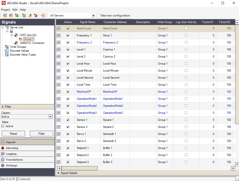
The Signal Group section
The grid columns represent the various signal properties (the properties can be edited in the grid):
UI Option | Description |
|---|---|
Active | If checked, the signal is active in WEBfactory Server. |
Signal Name | The name of the signal in WEBfactory Studio. The maximum length of the signal name (the maximum number of characters) is 256. |
Connector Address | The name (address) of the signal in the OPC server. The maximum length of the connector address (the maximum number of characters) is 256. |
Description | Optional signal description. |
Write Groups | The write group to which the signal belongs. |
Log User Activity | If checked, the user activity for this signal will be logged. |
Factor X1 | A real value of the PLC used to transform the signal value using a mathematical formula into a SCADA readable value Y1. The transformation is based on a XOY coordinate system and needs 4 values (X1, X2, Y1, Y1) to be applied. 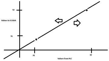 |
Factor X2 | A real value of the PLC used to transform the signal value using a mathematical formula into a SCADA readable value Y2. The transformation is based on a XOY coordinate system and needs 4 values (X1, X2, Y1, Y1) to be applied. |
Factor Y1 | The SCADA value of the X1 PLC value. The transformation is based on a XOY coordinate system and needs 4 values (X1, X2, Y1, Y1) to be applied. |
Factor Y2 | The SCADA value of the X2 PLC value. The transformation is based on a XOY coordinate system and needs 4 values (X1, X2, Y1, Y1) to be applied. |
Hysteresis | Sets an absolute (0.5) or relative (3%) minimum variation value for signal value visualization. The change of value will be displayed when the minimum variation is reached. Here, hysteresis refers to the difference between consecutive values of a signal. Only field-level signal values are taken into account. |
Log Hysteresis | Sets an absolute (0.5) or relative ( 3%) minimum variation value which is used when logging data in Float or Real format. The Log Hysteresis value will be used when the log condition for that signal is set to On Change. The signal value will be logged when the minimum variation value is reached. This option is useful when the OPC Server is sending values with many decimals. If the 9th decimal is changing, when the log condition is set to On Change, the new value will be logged. In this case, the difference might not be relevant to the user. Using Log Hysteresis, the user can define a value of minimum variation for the new value to be logged. The Log Hysteresis value can be absolute or relative. If both static and relative values are specified (eg. 0.5 AND 3%), the new value will be logged only if the change of value is more than 0.5 AND 3% from the previous value. Here, hysteresis refers to the difference between consecutive values of a signal. Only field-level signal values are taken into account. |
Alarm Hysteresis | Sets an absolute (0.5) or relative (3%) minimum variation value for alarm triggering. The alarm associated with the signal will be triggered when the minimum variation is reached. Here, hysteresis refers to the difference between consecutive values of a signal. Only field-level signal values are taken into account. |
Maximum | Sets the maximum signal value for writing. If a value bigger than this limit is written, the maximum value will be sent to the control unit. |
Minimum | Sets the minimum signal value for writing. If a value smaller than this limit is written, the minimum value will be sent to the control unit. |
Unit | Optional measurement unit for the signal's value. If present, the unit can be used further in visualizations. |
VChannel | Marks the signal as a virtual signal in WEBfactory 2010Studio. The virtual signal is created via a virtual channel (VChannel). The channel’s input parameters are signal variables. When the virtual channel is created, you define its input parameters (signal variables). Furthermore, you can create several virtual channels and link them to one another. The virtual signals can be used to manipulate the signal's value using VB scripts or to generate collective alarms. |
VChannel Type | Sets the VChannel type to Script or Collective alarm. |
VChannel Init Value | Sets a constant (named MyInitValue). When the system starts, the MyInitValue constant will be made available. |
Data Type | Set the data type for the WriteSignal () function. Can be:
|
Use Substitute Value | Enables the usage of the substitute values. If checked, a substitute value is used when the minimum value is not reached or the maximum value is exceeded. |
Substitute Value | The value of the Substitute Value. |
Assigned to Log(s) | Indicates if the signal is assigned to a log. |
Assigned to Alarm(s) | Indicates if the signal is assigned to an alarm. |
Discrete Value Type | The combining group of discrete values. The discrete values are used by WEBfactory Scheduler to manipulate a device depending on the hour of the day. The Discrete Value Type containing several discrete values can be attached to a process signal (in the Signal list) so that WEBfactory Scheduler can assign the value of one of the Discrete Values inside the Discrete Value Type to the process signal when needed. |
OPC enabled | Works in conjunction with the WEBfactory Server acting as an OPC server (usually the WEBfactory Server acts as an OPC client). When this option is enabled, the signal value will be sent to the WEBfactory WCS OPC server, so other OPC clients can access the value from the WEBfactory Server like from an OPC server. |
Right-clicking on a Signal Group in the Signals tree menu will open the contextual menu. The Group contextual menu provides options such as adding or deleting signals, browsing the connectors for signals or exporting and importing signals.
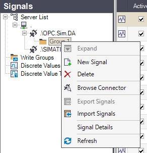
The Signal Group contextual menu
UI Option | Description |
|---|---|
Expand/Collapse | Expands/Collapses the clicked element. In the Group's case, the option is disabled because the Group cannot have any sub-items. |
New Signal | Allows the user to add a new signal to the signal group. |
Delete | Deletes the selected signal group. |
Browse Connector | Opens the Browse Connector dialog, allowing the user to add the signals available to the connector to the Studio project. |
Export Signals | Allows the user to export the signals belonging to the selected signal group to an XML file on the hard-drive. |
Import Signals | Imports signals from an XML file to the selected signal group. |
Signal Details | Toggles the Signal Details panel on or off. |
Refresh | Reloads the signal list. |
Right-clicking on a signal listed in the main panel while the a signal group is selected will open the contextual menu. The contextual menu allows the user to edit the cell from where the contextual menu was opened, manipulate signals (copy, move), create and delete signals and export or import signals.
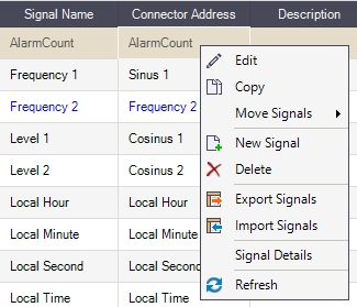
Contextual menu of selected Signal
UI Option | Description |
|---|---|
Edit | Edits the content of the cell where the contextual menu was triggered. |
Copy | Copies the selected signal(s) to clipboard, allowing the user to paste the clipboard content to another signal group. |
Move Signals | Allows the user to move the selected signal(s) to another group on the same connector or on a different connector. 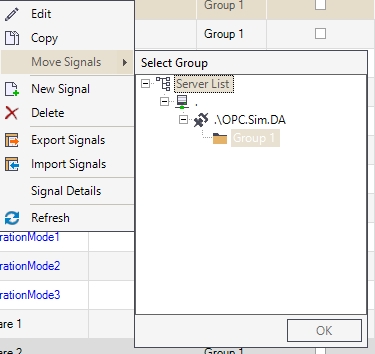 |
New Signal | Allows the user to create a new signal. |
Delete | Deletes the selected signal(s). |
Export Signals | Allows the user to export the selected signal(s) to an XML file on the hard-drive. |
Import Signals | Imports signals from an XML file to the current signal group. |
Signals Details | Toggles the Signal Details panel on or off. |
Refresh | Reloads the signal list. |
The Signal Details panel, located at the bottom of the main view, displays the complete set of signal properties. The same properties are available in the signals grid. For more details about the Signal Details Panel please also visit the next article.