SmartEditor Tutorials
Check out the WEBfactory 2010 SmartEditor tutorials and start using it to build your project visualizations.
Adding Static Symbols to SmartEditor
Check out this article and learn how to add a static symbol to the WEBfactory 2010 SmartEditor tool.
Creating a static symbol with Expression Blend - best practice
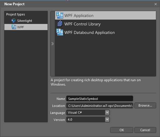
To create a static symbol that will be compatible with WEBfactory 2010SmartEditor, the Expression Blend project will need to be WPF and not Silverlight.
When using Transform tools (skew, rotate, etc.) in a Silverlight project, transformations will be stored in a CompositeTransform XAML tag, which is not compatible with WPF, thus with SmartEditor.
In the new WPF project, create the desired graphic. In our tutorial scenario, we will use three rectangles. Make sure that none of the elements of the symbol is named (delete the name= attribute from the XAML code).
Important
When creating static symbols for SmartEditor, avoid naming the elements! If a static symbol control with a named element is placed twice on the page (in the same project), the control will crash.
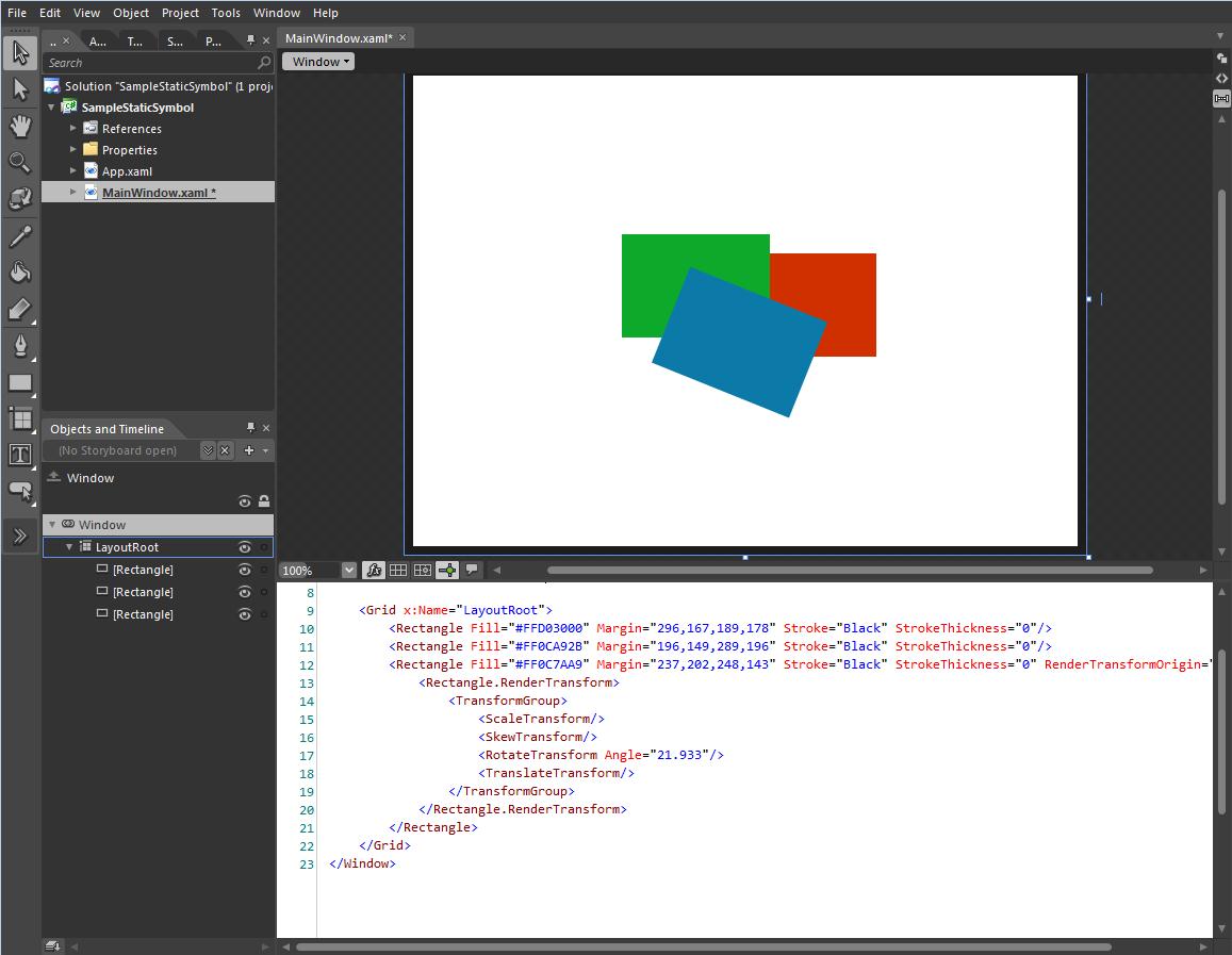
Notice that the transformation applied to the top rectangle is stored in the XAML code as RenderTransform and not CompositeTransform. The RenderTransform tag is compatible with Smart Editor.
The needed part from the WPF Expression Blend project is the XAML code of the grid, containing the graphical elements, combined in a Viewbox. Let us prepare the code for using it in SmartEditor:
Combine the graphical elements in a Viewbox (select all the elements > right click > Group Into> Viewbox
Delete the Margin attribute of the Viewbox.
Delete the Stretch attribute of the Viewbox.
The Viewbox is necessary in order to preserve the resizing capabilities in SmartEditor.
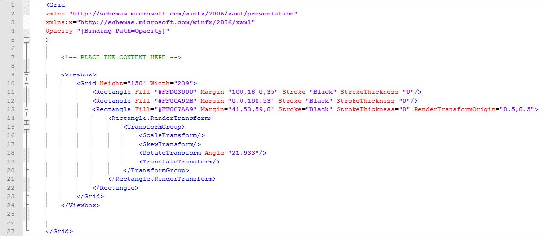
The code should look like this:
	<Viewbox>
			<Grid Height="150" Width="239">
				<Rectangle Fill="#FFD03000" Margin="100,18,0,35" Stroke="Black" StrokeThickness="0"/>
				<Rectangle Fill="#FF0CA92B" Margin="0,0,100,53" Stroke="Black" StrokeThickness="0"/>
				<Rectangle Fill="#FF0C7AA9" Margin="41,53,59,0" Stroke="Black" StrokeThickness="0" RenderTransformOrigin="0.5,0.5">
					<Rectangle.RenderTransform>
						<TransformGroup>
							<ScaleTransform/>
							<SkewTransform/>
							<RotateTransform Angle="21.933"/>
							<TranslateTransform/>
						</TransformGroup>
					</Rectangle.RenderTransform>
				</Rectangle>
			</Grid>
	</Viewbox>
The next step is to prepare the actual Windows Markup file that will contain the code of the static symbol. The safest method is to copy an existing static symbol and edit it. So head on to WEBfactory 2010 \SmartEditor\Views\StaticSymbols and copy one of the existing files. Paste the file in another folder and rename it.
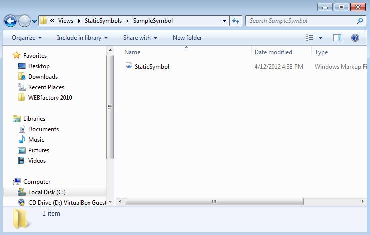
Open the new StaticSymbol file with the preferred editor. In our scenario, the original static symbol was Arrow_Red2.xaml.
Optional, the XAML can be edited using the Kaxaml freeware tool. Download Kaxaml here.
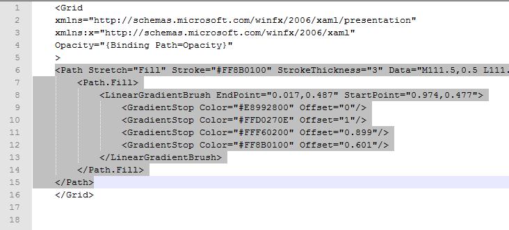
The part of the code that needs to stay in place is the Grid tag. Delete the other code (the selected code in the image above).
Optional, the StaticSymbol.xaml example file can be provided to you by the Support team.
Copy the Viewbox and all its content from the Expression Blend project, and paste it inside the grid, in the new StatiSymbol.xaml file, like in the example below:
Mapping the new static symbol control in SmartEditor
Now the xaml file needs to be mapped in SmartEditor. In order to do that, we will need to edit two files:
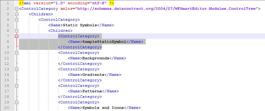
ControlCategories.xml
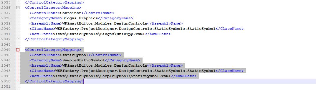
ControlMappings.xml
The two files can be found in WEBfactory 2010 \SmartEditor\Mappings.
Let us create the category for SmartEditor. Open the ControlCategories.xml file. Under the Static Symbols category, copy a subcategory, paste it and change the name of the category as desired.
Save and close the file.
Open the ControlMappings.xml. In this xml file, the actual xaml file we just created above will be linked to SmartEditor, in the category we defined earlier.
In the ControlMappings.xml, look for the mappings for static symbols. Copy one mapping, paste it and edit the ControlName, CategoryName and XamlPath attributes. Make sure to use the same naming conventions.
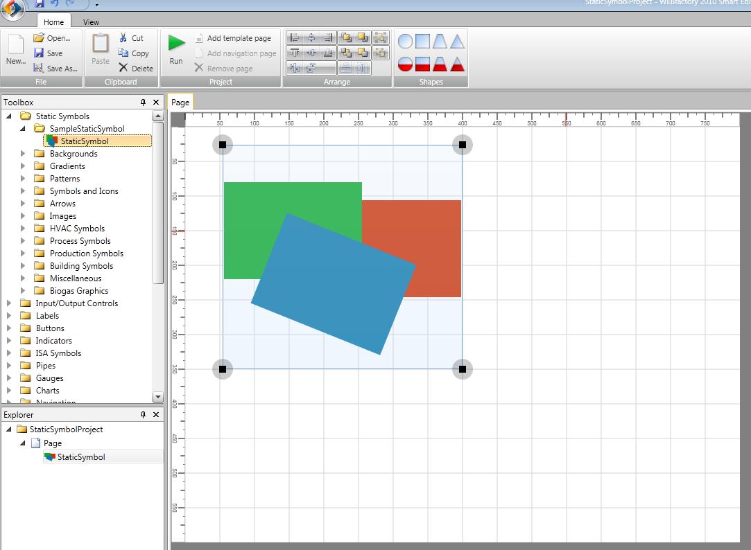
Save and close the file. At this point, the StaticSymbol control we created in Expression Blend is mapped and fully functional in SmartEditor.
Notice
Remember
Use WPF project in Expression Blend to design the static symbol control.
Make sure not to name any elements in order to avoid conflicts in SmartEditor.
Combine the elements of the static symbol control in a Viewbox.
Delete the Margin and Stretch atributes of the Viewbox.
Creating Master Pages for WEBfactory 2010 SmartEditor
Check out this article and learn how to create master pages for the WEBfactory 2010 SmartEditor tool.
In order to create a SmartEditor Master Page, we need to set up the initial SmartEditor project, save it properly and pack it along with an icon and a manifest.
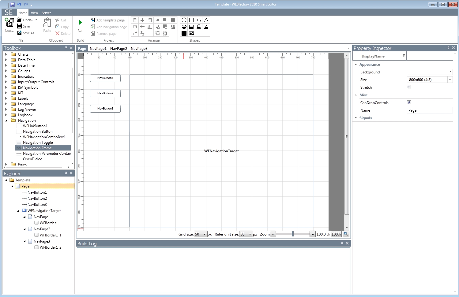
In WEBfactory 2010SmartEditor, create a new blank project and add the desired controls and navigation structure.
Tip
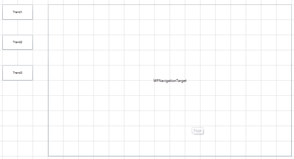
In the above example, the project contains a navigation structure composed of three Navigation Buttons, a Navigation Target and three Navigation Pages. Each Navigation Page contains a WFBorder1 control.
Save the project on the hard drive, using the name Template.
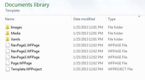
Place the new SmartEditor project called Template (the whole folder and it's contents) to a new folder. This folder is used just for collecting the required resources. Only the contents of this folder will be packed, not the folder itself.
Open the Template.WFProject file using a text editor (Notepad++ in our example). We will add the <MasterPage> tag on our main Page, in order to lock the controls on the page. Replace the <Page> tags (<Page> as well as </Page>) of the page you want to define as Master Page with the <MasterPage> tags (both <MasterPage> and </MasterPage>):
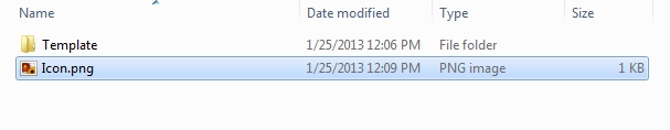
<Pages>
  <MasterPage> <!-- the former <Page> tag -->
      <Name>Page</Name>
      <Pages>
        <Page NavigationTarget="WFNavigationTarget">
          <Name>NavPage1</Name>
          <Pages />
        </Page>
        <Page NavigationTarget="WFNavigationTarget">
          <Name>NavPage2</Name>
          <Pages />
        </Page>
        <Page NavigationTarget="WFNavigationTarget">
          <Name>NavPage3</Name>
          <Pages />
        </Page>
      </Pages>
  </MasterPage> <!-- the former </Page> tag -->
</Pages>
Now that the main page is locked, add the Icon.png in the same folder with the Template project folder.
Note
Note that the icon must be 160 x 120 pixels, it must be named Icon and it must be a .png file!
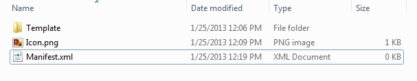
Now it's time to create the Master Page manifest. In the same folder, create a new text document using Notepad (or Notepad++). Name it Manifest.xml. Open the new xml file with the desired text editor and add the following code:
<ProjectTemplate Version="3.4.0.0">
	<Name>DemoMasterPage</Name>
	<Description>Creates a project with a navigation page and three navigation buttons linked to corresponding sub pages</Description>
</ProjectTemplate>
The code contains the version, name and description of the Master Page.
Now the contents of the Master Page folder should look like this:
To pack our project, icon and manifest into a SmartEditor Master Page (.sept), select the three different resources (Template folder, Icon.png and Manifest.xml) and create a .zip archive out of them.
The contents of the un-packed Master Page
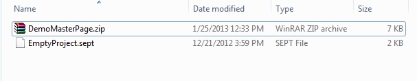
Change the extension of the .zip archive from .zip to .sept.
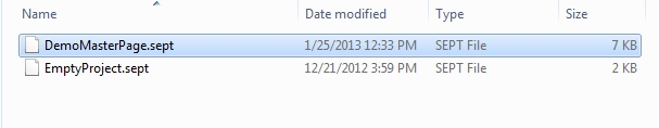
Important
Make sure that the new .sept file is placed in the WEBfactory 2010 \SmartEditor\ProjectTemplates folder.
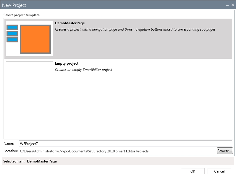
Create a new SmartEditor project. The new Master Page is available as a template project in SmartEditor New Project dialog.
Loading Trending configuration names as parameters
Check out this article and learn how to load trending configuration names as paramaters.
The WFTrending3 configuration names can be passed as parameters via navigation buttons. This method allows the user to create different WFTrending3 visualizations by using only one WFTrending3 control and adjust it's configuration for each page of the navigation.
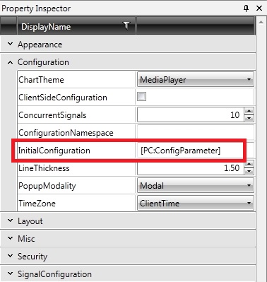
In order to use this parameter passing method, the WFTrending3 control must use a placeholder in the InitialConfiguration property.
Creating the navigation structure
In the new WEBfactory 2010SmartEditor project, add a WFNavigation button control on the Page. Add a WFNavigationTarget next to the button.
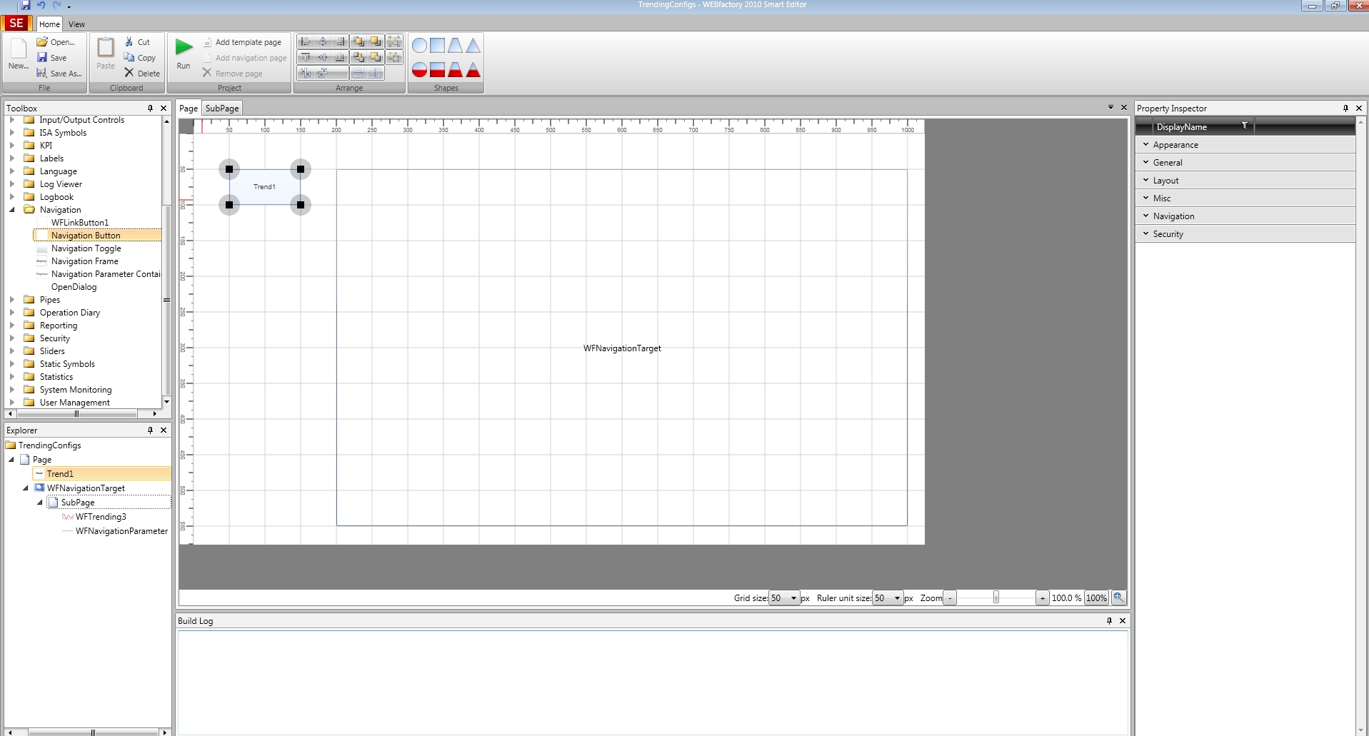
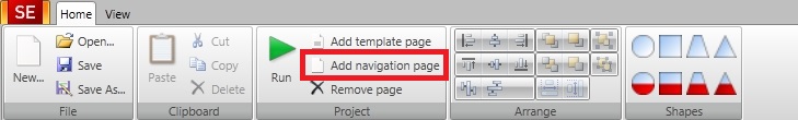
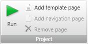
Now create a SubPage by clicking on the Add navigation page button from the Ribbon bar.
On the new SubPage, place a WFTrending3 control and a WFNavigationParameter control.
Setting up the parameters
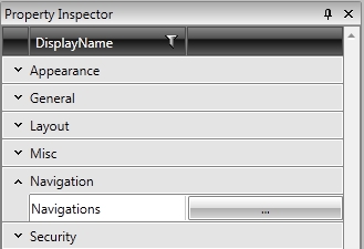
In the main Page of the project, select the WFNavigation button control and expand the Navigation properties category from the Property Inspector. Click on the button corresponding to the Navigations property.
In the Navigations Edit Items window, add a new navigation item by clicking on the Add NavigationItem button.
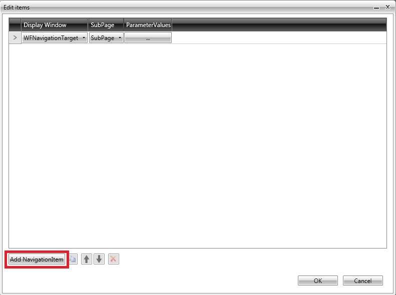
Choose the WFNavigationTarget from the Page as Display Window and the previously created navigation page as the SubPage. Click on the ParameterValues button to create the needed parameter for our navigation item.
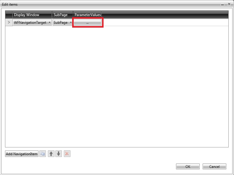
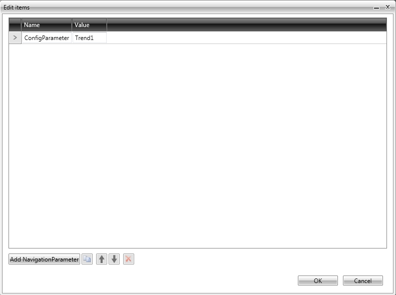
In the ParameterValues Edit Item window, create a new parameter by clicking on the Add NavigationParameter button. In the new parameter, add the name and the parameter value.
The parameter value should be the name of the desired Trending configuration to be applied when clicking this navigation button. The trending configurations to be used must be existing as saved configurations in the WFTrending3 control at run time.
Confirm the dialogs. Now duplicate the WFNavigation button control and change the parameter value to be the next Trending configuration needed to be loaded by the second button. Do the same for as many Trending configurations as needed.
Head in the navigation SubPage, where the WFTrending3 control is placed. Select the WFTrending3 control and head in the Property Inspector. Expand the Configuration category and place the [PC:ParameterName] placeholder in the InitialConfiguration property text field. Replace the ParameterName text with the name of the parameters passed by the three navigation buttons - ConfigParameter in our example.
Run the application and click the three buttons. Each button will trigger the display of the same control but with different configurations.
Deploying SmartEditor projects to IIS
Check out this article and learn how to deploy your WEBfactory 2010 SmartEditor projects to IIS.
In order to run any visualization project created with SmartEditor, the project must be deployed to Internet Information Services.
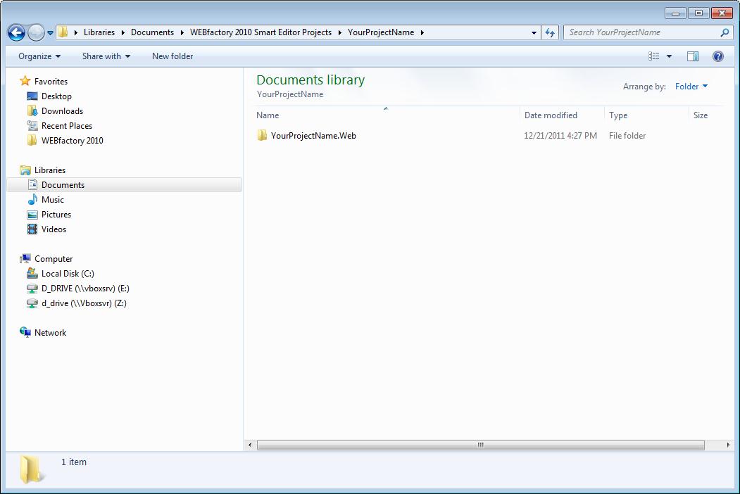
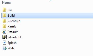
The first step after the project is built in SmartEditor is to navigate to C:\Users\UserName\Documents\WEBfactory 2010SmartEditor Projects\YourProjectName and copy the folder YourProjectName.Web to C:\inetpub\wwwroot.
YourProjectName is an example name. This will be replaced with the name of your project.
After the folder is copied, delete the Build folder inside the YourProjectName.Web folder from wwwroot.
Some specific visualization applications may require additional settings to be done in IIS. See Deploying the User Manager Visualization to IIS for reference.
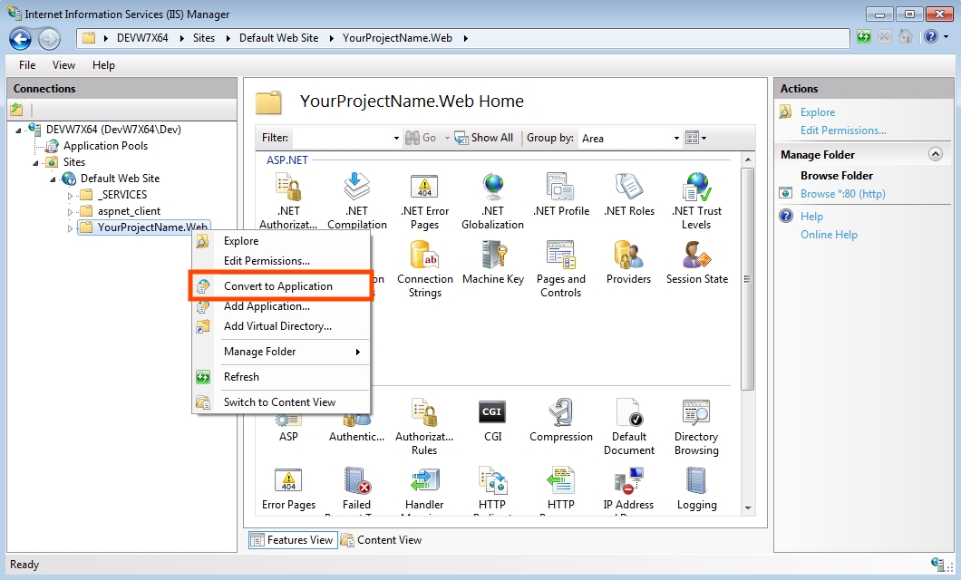
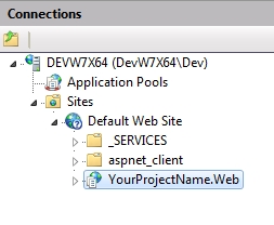
Now it is necessary to convert the build project to a web application. To do so, open Internet Information Services (IIS) Manager from Control Panel > System and Security > Administrative Tools.
In the left panel, under Sites > Default Web Site, the YourProjectName.Web folder will be available.
Right click on the project folder and select Convert to Application.
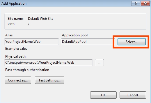
In the Add Application window, click on Select... .
Select WEBfactory 2010_AppPool from the Application Pool drop-down menu and press OK.
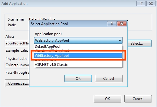
Confirm the Add Application dialog by pressing OK. The folder inside the Connection panel will change into an application.
Running the new application
To run the new application, go to Content View in IIS, right-click Default.html and select Browse.
To access the application from a remote machine via local network or Internet, open a web browser and access the IIS root folder using the HTTP protocol:
http://[computer name or IP]/YourProjectName.Web/Default.html
[computer name or IP] designates the actual ip/computer name of the machine running the IIS.
If the application will be accessed via Internet or from a location that is in a different network than the machine running the IIS, the router must be configured in order to allow access to the IIS from outside the local network (port forwarding).
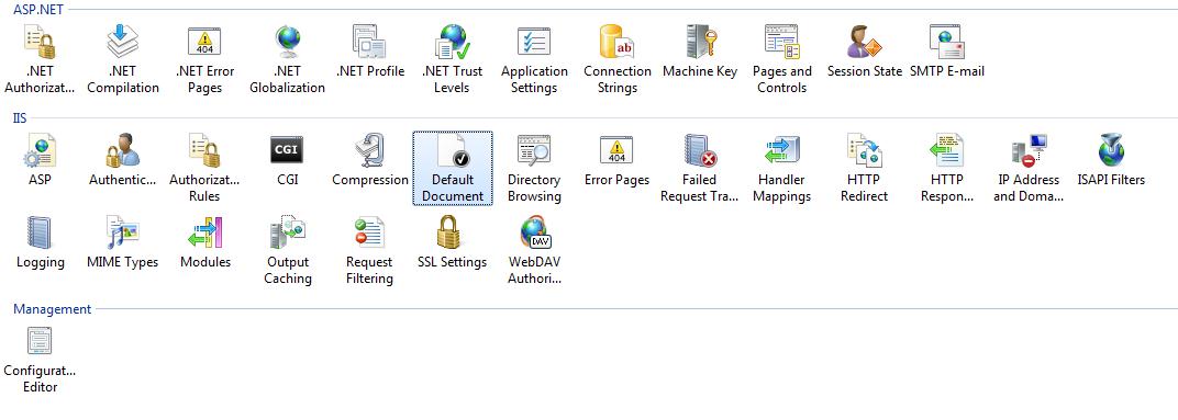
To access the application without specifying html document at the end of the URL, the next settings must be made:
In IIS Features View, go to Default Document options under IIS category.
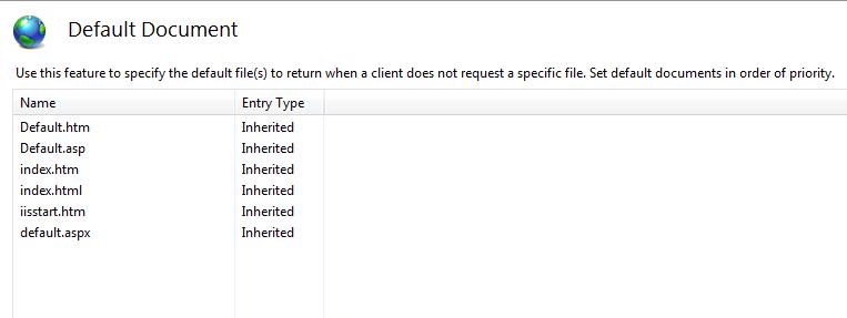
In Default Document, you can see that there already is a Default.htm defined at the top of the list. As our document has the html extension and not the htm, we will need to add Default.html on top of the list, as default document.
The order if the documents in Default Document in the list matters; IIS will first look for the first document, and if that document doesn't exist, will look for the second, and so on.
Right click in the Default Document window and select Add. In the dialog, enter "Default.html" and select Ok.
Now the application can be accessed from the web browser by typing the URL without the "Default.html" part:
http://[computer name or IP]/YourProjectName.Web
The process of deploying is complete. Now the application can be accessed from any location.
Using Template Pages in WEBfactory 2010SmartEditor
Check out this article and learn how to use template pages in your WEBfactor 2010 SmartEditor projects.
Template Pages in SmartEditor are the pages displayed by pop-up windows. They can contain information or other controls.
Pop-up windows are supported by a range of control categories:
Labels
Indicators
ISA Symbols
Primitives
Next we will discuss the creation of a simple Template Page pop-up and the passing of parameters.
Creating a simple Template Page pop-up
To create a pop-up window using Template Pages, open SmartEditor and create a new project. From the Ribbon, select the Add template page button. This adds a new TemplatePage to your project.
Adding a Template Page
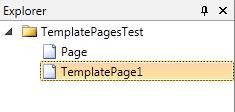
The TemplatePage is added to the Explorer panel
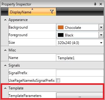
The Template Page exposes several properties in SmartEditor. Select the Template Page just created, and go to the Property Inspector.
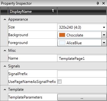
Template Page properties
SmartEditor allows the user to modify the Size of the Template Page, the Background and Foreground colors and the Name. Signal properties are also available: SignalPrefix and UsePageNameAsSignalPrefix.
As the SignalPrefix property is plain simple (add a signal prefix for more complex parameter passing), the UsePageNameAsSignalPrefix allows the user to use the same text from the Name text field as signal prefix.
The last property, TemplateParameters, allows the user to set parameters for the template.
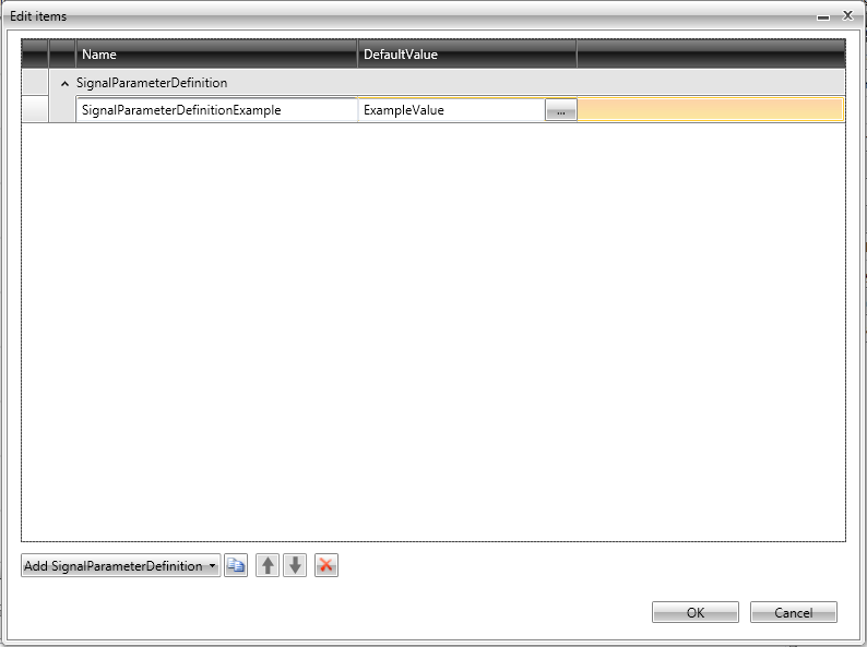
Template parameters
When a adding a parameter to a Template Page, the user can define Name and a DefaultValue.
Now that we have the Template Page, we must create a control that will show the template page. From the Toolbox, drag on the Page (not on the TemplatePage) a Text Label control.
Select the Text Label control and go to the Property Inspector. The last category will be Template.
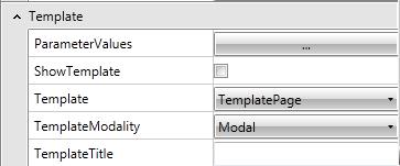
Any control that supports Templates (or pop-ups) will display the following properties:
ShowTemplate - enables or disables the pop-up behaviour
TemplateModality - toggles between modal and modeless pop-up behavior.
Modal - the pop-up window will appear on top of the page, and will block access to the elements behind it, until it is closed.
Modeless - the pop-up window will appear on top of the page, allowing the user to see and click on the elements behind it.
Template - allows the user to chose what Template Page the pop-up should display.
TemplateTitle - title for the template page.
ParameterValues - allows the user to set the parameter values for the parameters previously set in the Template Page.
Enable the pop-up behavior by checking the ShowTemplate checkbox.
Chose the modality of the pop-up window, and select the Template Page created above.
Press Run in the Ribbon or hit F5 to run the visualization.
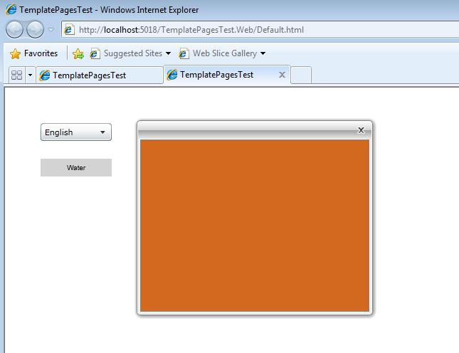
Upon pressing the label indicator, the Template Page will pop up, using the selected modality.
Now that we understand the basics of Template Pages in SmartEditor, let's proceed to a more advanced step: parameter passing.
Passing parameters in Template Pages
Defining parameters
To use parameters in Template Pages, the template page must have parameters defined. To define a parameter for the Template Page, select the Template Page and go to the Property Inspector > TemplateParameters.
Click on the button corresponding to the TemplateParameters option to open the Template Parameters window.
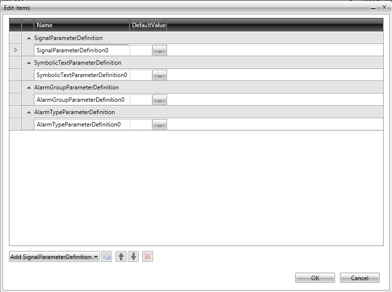
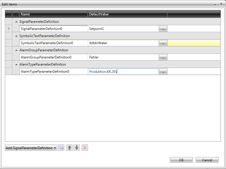
To define a new parameter, click on the Add SignalParameterDefinition button from the bottom-left side (click on the arrow to expand the dropdown button for more parameters). Add one of each type of parameters:
SignalParameterDefinition - passes the signal name as parameter
SymbolicTextParameterDefinition - passes a symbolic text as parameter. It is used to create placeholders.
AlarmGroupParameterDefinition - passes an alarm group as a parameter. It is used when the Template Page holds an Alarm Viewer or Alarm Online control.
AlarmTypeParameterDefinition - passes an alarm type as a parameter. It is used when the Template Page holds an Alarm Viewer or Alarm Online control.
Name the parameters as desired, and select a DefaultValue. For demonstrative purposes, the names will be left as default in this tutorial.
The DefaultValue will be the value that the pop-up window will pass through this parameter if no other value is assigned from the launcher control. The user can create as many parameters as needed.
Select OK to confirm.
Using the defined parameters in controls inside the Template Page
To use this parameters inside the Template Page, we must drag some controls on the page surface and assign the parameters to them, instead of assigning a real values (signals, symbolic texts, alarm groups or alarm types).
Select WFExtendedNumericDisplay1 , WFSignalInformationLabel1 , WFLabel1 and WFAlarmOnline control, and place them on the Template Page.
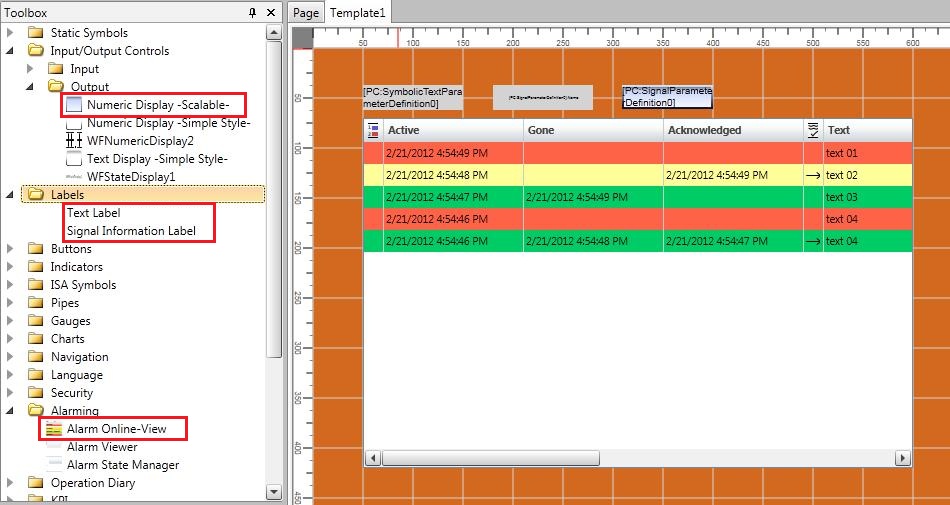
Select the first two controls (WFExtendedNumericDisplay1 and WFSignalInformationLabel1 ) and go to the Property Inspector > Signals and set the SignalName to be the SignalParameterDefinition0 defined for the Template Page.
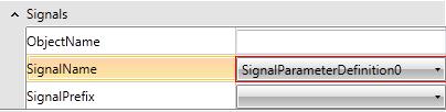
Now, the WFExtendedNUmericDisplay control and the WFSignalInformationLabel control will display values for the signal passed through the parameter (name and value).
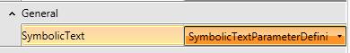
Select the third control (WFLabel1) and goto Property Inspector > General, and set the SymbolicText to the corresponding parameter.
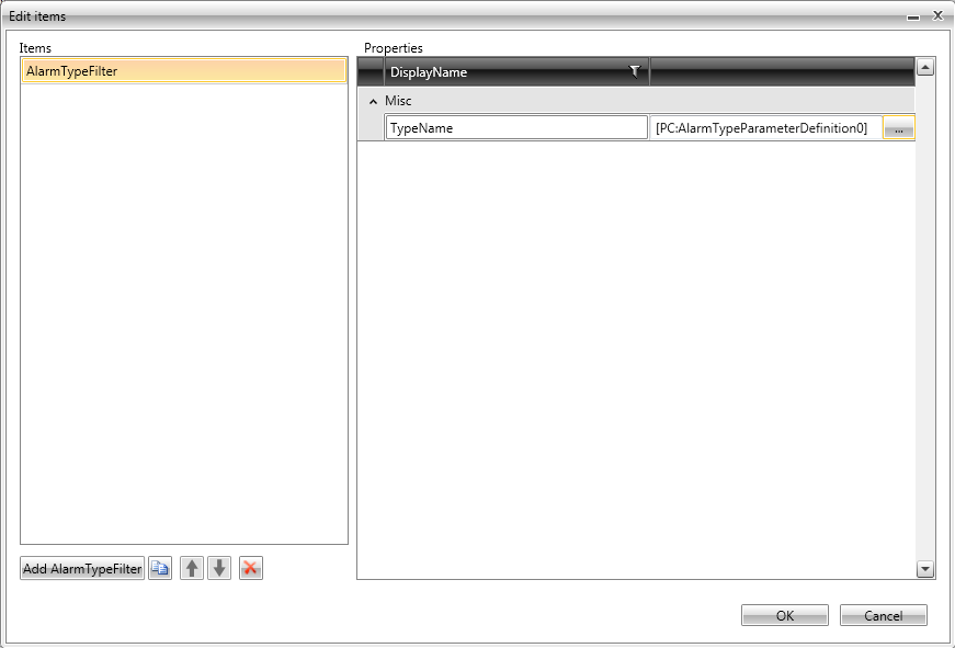
Select the WFAlarmOnline control and go to Property Inspector > Configuration to set the group filters and type filters to use the defined parameters:
GroupFilter - AlarmGroupParameterDefinition0
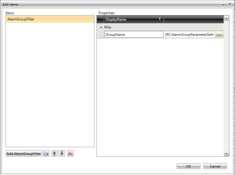
TypeFilter - AlarmTypeParameterDefinition0
But the useful part is yet to come. Next, we are going to use the Template Page parameters in the control that launches the Template Page pop-up, inside the main Page.
Assigning values to parameters
On the main Page, select the label control that launches the Template Page. In the Property Inspector, go to Template category and select ParameterValues.
The parameters defined in the Template Page are listed in the Template Parameters Value Editor window, and the Values are editable. By selecting other values, the new values are passed to the Template Page and to the controls inside that Template Page.
Leave the values as default, and drag another WFLabel1 on the surface of the Page. Enable the Template pop-up, select the same Template Page. In the Template Parameter Value Editor of this new control, assign different values for the parameters.
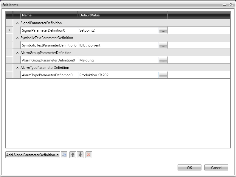
When the first Label control is clicked, it will open the pop-up window displaying the Template1 Template Page, with the default values for the parameters. When clicking the second Label control, pop-up will open the same Template1 Template Page, but passing the values assigned in the ParameterValues option of this second Label control.
This means that both Label controls use the same Template Page, but each one passes different values.
Press F5 or the Run button to test the visualization with the default parameter and with the new parameter value entered in the second Label control ParameterValues option.
Working with Themes in WEBfactory 2010SmartEditor
Check out this article and learn how to work with WEBfactory 2010 SmartEditor themes.
The following example will guide you through the necessary steps of setting up theming and applying it on a SmartEditor control.
Creating the themes
Select the Project (top level parent) in the Explorer panel of SmartEditor. In the Theming properties category (from the Property Inspector panel), click on the Themes button to open the Themes editor window. Click on the Add ThemeDefinition button to add the desired number of themes. Name the themes and apply the default one. Click OK to confirm.
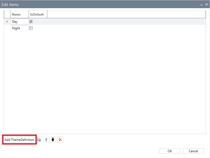
Creating the themes in SmartEditor
In out example, we have created two themes (Day and Night), each one for a half of a 24 hour cycle.
Creating the brushes for the two themes
In the Theming property category, click on the ThemableBrushes button to open the editor window. Use the Add ThemableBrush to add the new brushes. Click on the color of each brush to select the desired color using the color picker. Click OK to confirm.
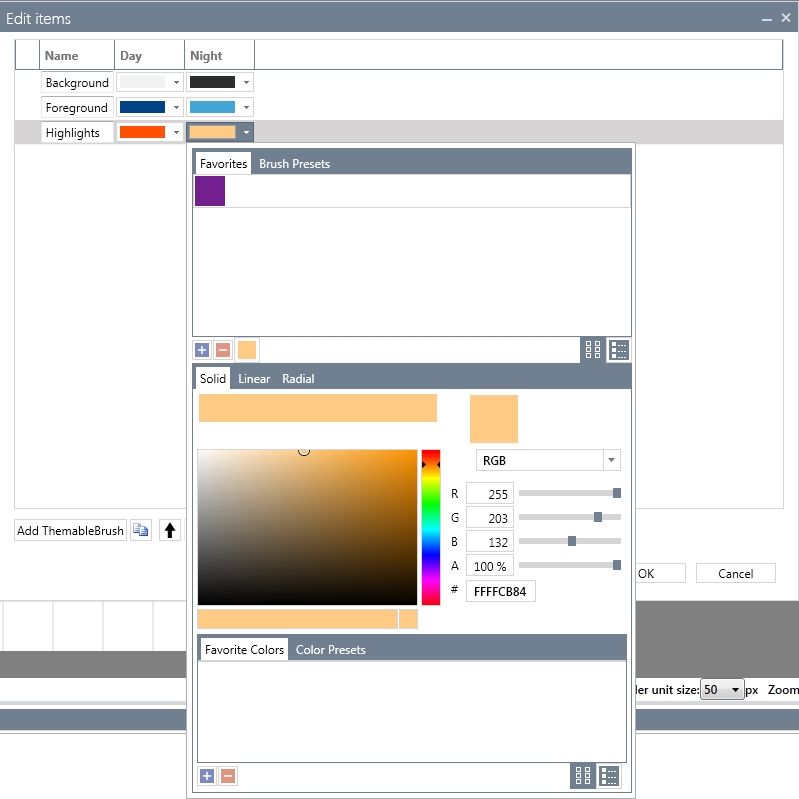
Selecting the brush colors using the color picker
In our example, we have created three different brushes: Background, Foreground and Highlights.
Creating the conditions for applying the themes
In the Theming property category, click on the ThemeConditions button to open the editor window. Use the Add ThemeCondition to create a condition for each theme and set up the desired conditions:
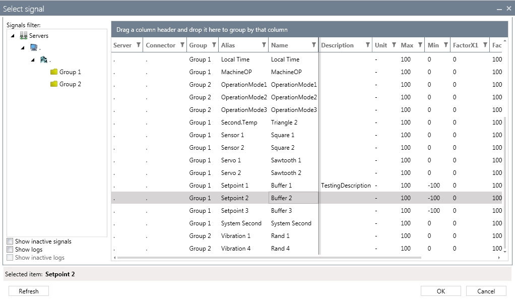
Select the Signal to be used by clicking the button corresponding to the SignalName column.
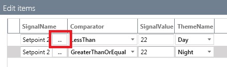
Select the desired signal using the Signal Browser and click OK to confirm.
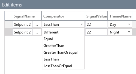
Select the desired comparator by clicking on the drop down menu from the Comparator column.
Place the constant value that will be compared to the signal's value in the SignalValue text field.
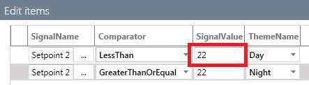
Select the theme which will be applied if the condition is met.
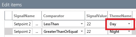
In our example, we have defined two theme conditions. The first theme condition applies the Day theme if the signal value is lower than 22. The second theme condition applies the Night theme if the value of the signal is equal or greater than 22 (considering a 24 hour day, the 22 hours would mark the beginning of the night).
Click OK to confirm the ThemeConditions editor window and save the configuration.
Applying the themes on the WFCompass1 control
Place a WFCompass1 control on the WEBfactory 2010SmartEditor Page. Select the control and head in the Appearance property category from the Property Inspector panel.
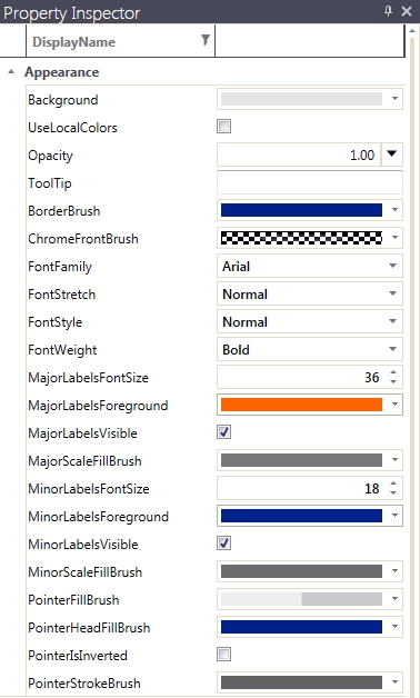
The Appearance properties of the WFCompass1 control
Select the previously created brushes from the color picker to match the control's properties:
the Background brush in the Background property,
the Foreground brush in the BorderBrush property,
the Highlights brush in the MajorLabelForeground, MinorLabelForeground and PointerHeadFillBrush properties.
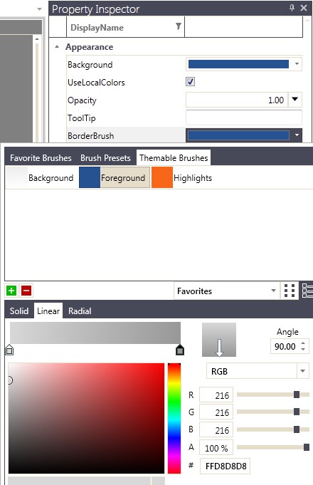
Selecting the themable brushes
Run the visualization and change the signal's value (Setpoint 2 in our example) to be lower than 22 and equal/higher than 22.


The two different themes applied (Day theme: Setpoint 2 value < 22, Night theme: Setpoint 2 value >= 22)